10. Structured illumination microscopy#
Structured illumination microsocpy (SIM) generates images with improved optical sectioning and/or resolution by illuminating the sample with spatially varying intensities. There are many different ways the illumination can be structured, the most common excitation schemes fall either under interference-based or laser scanning-based illumination.
Image formation under illumination of the sample with a pattern is described by the multiplication of the sample’s fluorescence distribution with the pattern, followed by convolution with the incoherent widefield microscope point spread function.
where \(F(\vec{x})\) is the spatial distribution of fluorescence lables, \(I_{ill}(\vec{x})\) is the structured illumination pattern and \(\text{psf}(\vec{r}) = |h(x,y)|^2\) is the incoherent point-spread function of the imaging setup.
Note
If you want to read up more about SIM microscopy, I recommend the following reviews and protocol papers:
Wu, Y., Shroff, H. Faster, sharper, and deeper: structured illumination microscopy for biological imaging. Nat Methods 15, 1011–1019 (2018).
Demmerle, J., Innocent, C., North, A. et al. Strategic and practical guidelines for successful structured illumination microscopy. Nat Protoc 12, 988–1010 (2017).
Ying Ma et al 2021, Recent advances in structured illumination microscopy, J. Phys. Photonics 3, 024009
This chapter on SIM loosely follows M. Fazel, K. S. Grussmayer, B. Ferdman, A. Radenovic, Y. Shechtman, J. Enderlein, S. Pressé, Fluorescence Microscopy: a statistics-optics perspective, [OA, arXiv:2304.01456].
10.1. Interference-based structured illumination#
The classic SIM implementation uses sinusoidal illumination under different in-plane angles and with different pattern phases generated by the interference of two or three laser beams with the help of e.g. a grating that is rotated and translated, and detection of the in focus plane on a camera. For two-beam interference, the image formation is as follows.
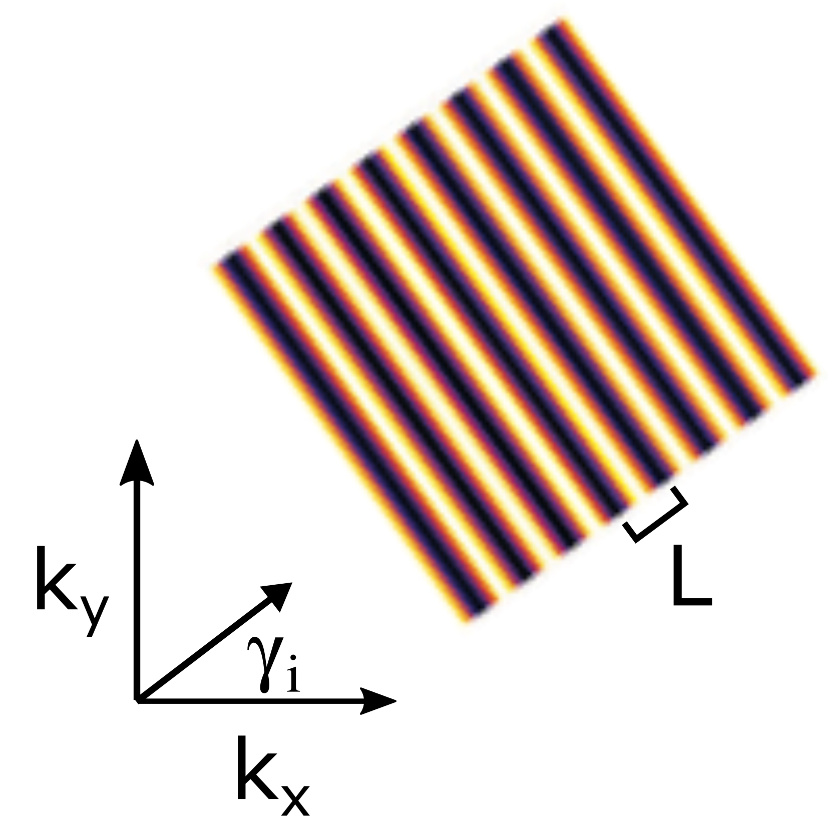
Fig. 10.1 Sinusoidal illumination pattern as used in interference-based SIM.#
where \(\vec{k}_i\) is the wave vector defining the period of oscillating pattern L and the in-plane angle of the illumination \(\gamma\) and \(\phi\) is the phase offset determing the position of the maxima relative to the optical axis.
10.2. Optical sectioning SIM#
A major drawback of widefield fluorescence imaging is the lack of optical sectioning, i.e. for each focal plane out-of-focus blur from other sample regions contributes to the image. This is due to the missing cone of the optical transfer function (OTF), that does not allow to axially resolve low spatial frequencies. Neil and others introduced a simple approach to achieve sectioning by imaging a grid pattern that has a high stripe contrast only near the focal plane. Thus, the illumination intensity of an in-focus point in the sample varies strongly with the pattern position, but becomes more homogeneous for greater distances from the focus. By translating the pattern using three phases, an image can be reconstructed e.g. according to equation, where the contribution from the unmodulated out-of-focus component is rejected. This is a straightforward and fast approach for optical sectioning SIM, and different implementations of illumination and reconstruction are possible.
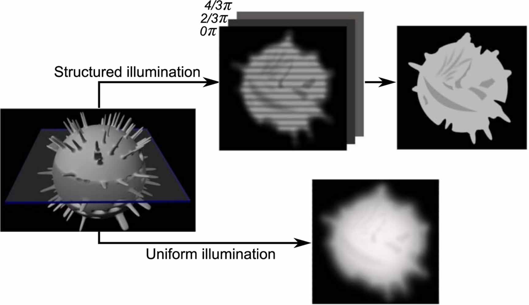
Fig. 10.2 The principle of optical sectioning SIM. Optical sectioning is achieved by translating the structured illumination, out-of-focus blur is effectively rejected because it is not modulated by the SIM pattern. The figure corresponds to figure 2 of Ying Ma et al…#
10.3. Interference-based super-resolution SIM (in 2D)#
The same sinusoidal illumination pattern that is used to obtain optical sectioning can be applied to enhance the spatial resolution. The principle idea behind the resolution improvement exploits the Moiré effect (frequency mixing) between the excitation pattern’s and the sample’s spatial frequencies to shift down previously unobservable high-frequency information of the sample, which is beyond the support of the widefield OTF, into the microscope’s passband.
10.3.1. Classical SIM reconstruction#
The effect of the illumination of the sample with a sinusoidal pattern is best examined in Fourier space and corresponds to a convolution of the Fourier representations of the sample and illumination pattern (three peaks).
We see that the illumination added two copies of the Fourier representation of the sample \(F(\vec{k})\) to the object spectrum, phase shifted by a factor \(\phi\) and frequency shifted by \(\vec{k}_i\) compared to widefield microscopy. If we simplify the effect of the OTF to act as an ideal low-pass filter with a cut-off frequency \(k_c\) , we see that the frequency shifted components contain high frequency information that is not present in the central component (sum frequency \(\vec{k} + \vec{k}_i\) and difference frequency \(\vec{k} - \vec{k}_i\) at each sample frequency of \(k\)). When imaged, only frequencies inside the support of the widefield OTF are captured. However, sample information from different (higher) frequency regions are now lying within the microscope’s passband.
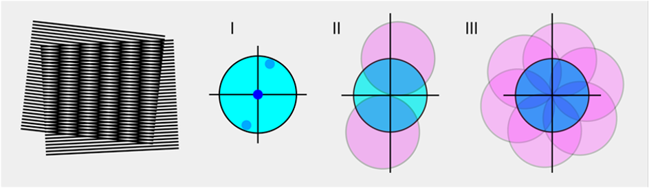
Fig. 10.3 The principle of super-resolution SIM. Left: illustration of the Moire-effect of frequency mixing. Middle: (I) Schematic widefield OTF boundaries and the three peaks in Fourier space where the structured illumination adds shifted OTF copies (II) for one angle of the illumination pattern. Right: 360 degrees coverage in Fourier space when all three illumination patterns at different angles are overlaid for isotropic resolution gain in the xy-plane.#
The three components \(I_0\), \(I_+\), \(I_-\) (widefield, \(\pm\) pattern wave vector) are overlapping and no sub-diffraction resolution can be achieved at this point. In order to unmix the components, we need to acquire at least three images with different pattern phases \(\phi\). The non-trivial step in the reconstruction of a SIM image is the accurate estimation of the pattern frequency, phases and the stripe contrast (here assumed to be 1 for simplicity).
The relation between the three OTF components and the measured spectra \(I(\vec{k}, \phi)\) is best shown in matrix form. Here, we use an idealized mixing matrix, with different phases for the available spectra evenly spaced between \(0\) and \(2\pi\).
The unmixed components are then recombined by shifting them so that their true zero frequency is aligned with the zero frequency in Fourier space. This yields an effective OTF which has been extended to frequencies beyond the support of the original OTF, i.e. the resolution of the SIM image is then \(k_c + k_i\) along the direction of \(\vec{k}_i\). Just like the imaging PSF the illumination pattern is also diffraction limited; its corresponding Fourier peaks are lying within the support of the systems OTF, limiting the resolution improvement to a factor of about two (considering e.g. the Stokes shift of fluorescence emission). The process has to be repeated for at least three orientations in order to achieve near isotropic lateral resolution enhancement.
10.3.2. Varying the illumination depth#
Resolution improvement using SIM can also be combined with illumination modalities other than widefield epifluorescence that provide physical optical sectioning, such as TIRF, gracing incidence illumination or light-sheet microscopy.
10.3.3. SIM hardware implementations#
As mentioned above, interference-based SIM can be implemented using phase gratings in the conjugate sample plane that are rotated and displaced. This hardware implementation is limited in speed (~1 fps) by the movement of the grating and requires different gratings for multicolor image acquisition. Fast SIM (~100 fps) often uses spatial light modulators (SLM) to overcome these issues. The patterns are displayed using a pixelated grid and intricate polarization control is necessary in the case of liquid crystal displays and the blazed grating effect needs to be taken into account for digital micromirror devices. To overcome the high illumination losses of SLMs e.g., the patterns can also be generated using galvanometric mirror(s) to control the pattern period and orientation and mirrors on piezo stages to introduce the phase shifts.
10.3.4. Non-linear SIM#
All implementations of structured illumination microscopy that we mentioned so far use linear fluorescence excitation. This has the advantage of being relatively gentle to living samples because low excitation intensities can be used compared to other super-resolution imaging methods and allows recording time-lapse image series.
As described above, linear structured illumination improves the resolution only up to approximately twofold, because the illumination pattern itself is limited by diffraction. A higher resolution can be obtained once we make use of nonlinear photophysics of fluorophores that cycle between different states (see STED/RESOLFT) to create patterns that contain higher spatial frequencies than the widefield cutoff \(k_c\). The nonlinearity can be described as a series of harmonics with spatial frequencies that are multiples of \(k_c\), potentially providing unlimited resolution improvement. The principle behind the resolution improvement is the same as for linear SIM, but frequency mixing now provides more displaced OTF components in Fourier space that require more images with shifted pattern phases to be seperated.
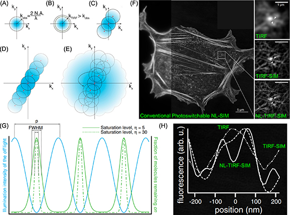
Fig. 10.4 The principle of non-linear SIM (D,E,G) and comparison to linear SIM (A,B,C). Nonlinear SIM based on photoswitchable protein and its application in imaging filament structures in actin network (F,H). This figure corresponds to figure 7 of Ying Ma et al…#
Similarly, this process has to be repeated at more angles to achieve isotropic lateral resolution. Photoswitchable fluorescent proteins (reference chapter chemistry) can be used that cycle between dark and bright states at much lower intensities and are more live-cell compatible. By superimposing structured off- or on-switching with excitation patterns, a finer fluorescence pattern and similar resolutions compared to saturated SIM can be achieved for limited time-series. The switching leads to more pronounced photobleaching compared to linear SIM. This, together with the inherent need for more images in the reconstruction, makes nonlinear SIM currently a niche application.